In my mission of publishing some of my old projects, I decided to publish my non-Euclidean Grid renderer. In this post, I attempt to explain the intricacies of the rendering procedure. Also, check out the demo and the source code.
We live in a world with Euclidean space. When I move 3 steps to the right, followed by 2 steps forward, I end up in the same position as when I first take 2 steps forward, followed by 3 steps to the right.
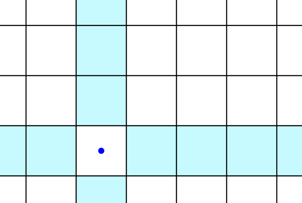
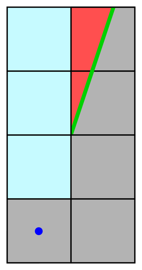
Now, imagine this property is absent. Envision a world where the order of movements does affect where you end up. What would it look like? I do not know, but I can give you my interpretation when it concerns a grid-based world. Imagine yourself being the blue dot in the image below. You’re standing on a tile, but depending on the direction you look, you see different things. Whatever you see beyond the tile’s north face need not be connected to whatever is located beyond the east face. Think of this as being surrounded by four portals, each of which transport you somewhere different.
These other worlds also consist of similar tiles, each of which with its own four portals. It is almost impossible to navigate this world, as your position in the world is poorly defined. You are in a universe of portal-connected fragments. To make it somewhat less surreal, I will stick to examples that mostly obey Euclidean space, with an occasional portal. That also makes more sense for any applications of this technique.
As the objective is to render such a mysterious world, I will guide you through the steps I took to implement this.
The Data Structure
Let’s start with the data structure that can represent this.
Clearly, a regular two-dimensional array containing each tile will not work. After all, the tiles are not neatly stacked along the axes. Instead, the tiles are stored in a two-dimensional doubly linked list. This effectively means that each tile contains a pointer to the nodes adjacent to it, with the additional constraint that if a tile’s face  connects to another tile’s face
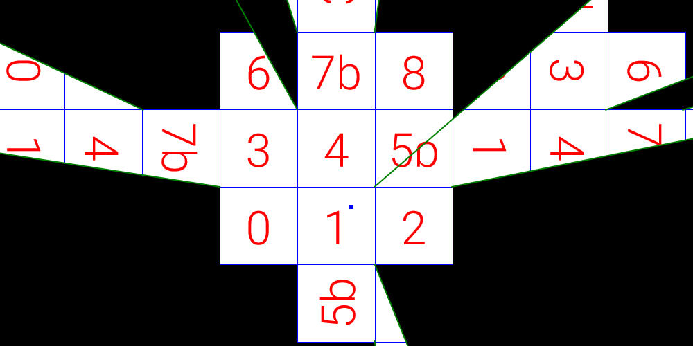
  , then must also point to . A depiction of one such structure is shown below.
As it is a two-dimensional “grid”, every tile tile has a north, east, south, and west face. In this example, most tiles actually satisfy the property of euclidean space, with the exception of tiles  and
and  . Namely, from the perspective of tile
  , tiles and appear to occupy the same spot.
Rendering
For rendering, I use the HTML5 2D Canvas with its clipping capabilities. Clipping restricts rendering within a custom shape, which is a common operation in rendering APIs.
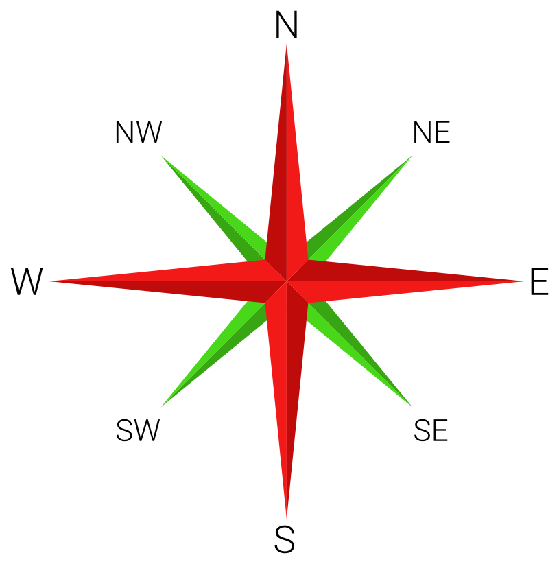
Rendering starts with a single root tile. The entire scene is rendered as if seen from the root tile; this is done through mutually recursive functions that render only fragments of the entire scene. Note that I use the terms cardinal and intercardinal directions. A cardinal direction is either North, East, South, or West. An intercardinal (sometimes called ordinal) direction is either North-East, South-East, South-West, or North-West.
Rendering Cardinal Directions
Rendering the tiles along the cardinal directions is trivial. No matter the user’s position in the root tile, the tiles along any cardinal direction are visible as if it were a corridor. Thus, starting from the root tile, one such corridor is rendered by traversing the linked list along a particular cardinal direction. As the world could be infinite, rendering should terminate upon reaching the edge of the screen.
Rendering Intercardinal Directions
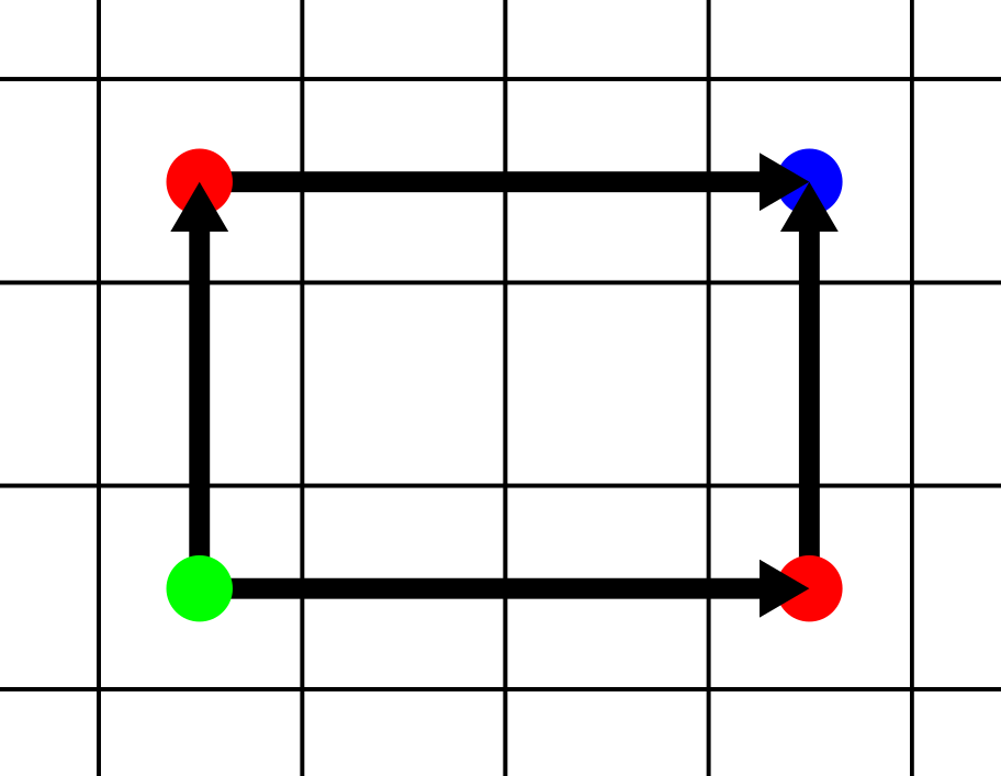
Rendering the section toward any intercardinal direction from the root gets trickier. Consider the image below.
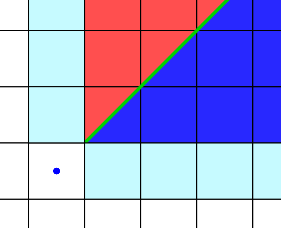
The tile reached from going North-East is different from the tile reached from going East-North. This phenomenon I refer to as an intercardinal split. If such a split occurs, the upper and lower sections must be individually rendered. These region are bounded by the half-line originating from the (in this case) bottom-left corner of the split tile. This half-line bounds the clip-regions.
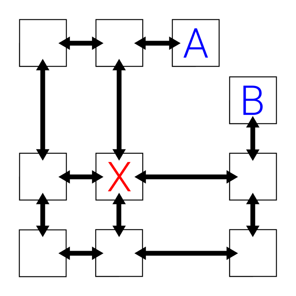
From the root, a large part of the north-east region can be seen. That region may also contain further intercardinal splits. Thus it is reasonable to render the intercardinal region, starting from the tile above the current root. This is depicted in the image below.
For this new root, a new eastern corridor is visible, which must be rendered appropriately (akin to any cardinal corridor). A procedure similar to the one used for rendering the original root can be applied to the new root (pink), to render its intercardinal (North-East) region.
The region reached by going East-North from the (original) root is rendered with a similar procedure. That region is, of course, bounded from above by the half-line.
Rendering Hanging Regions
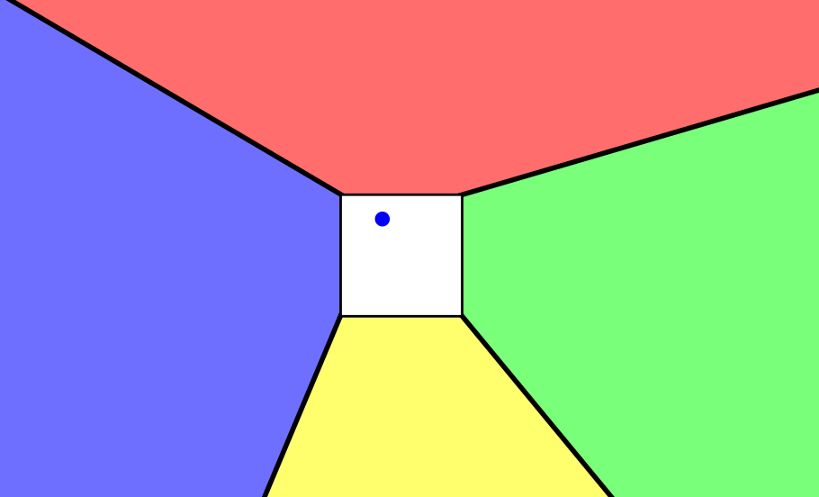
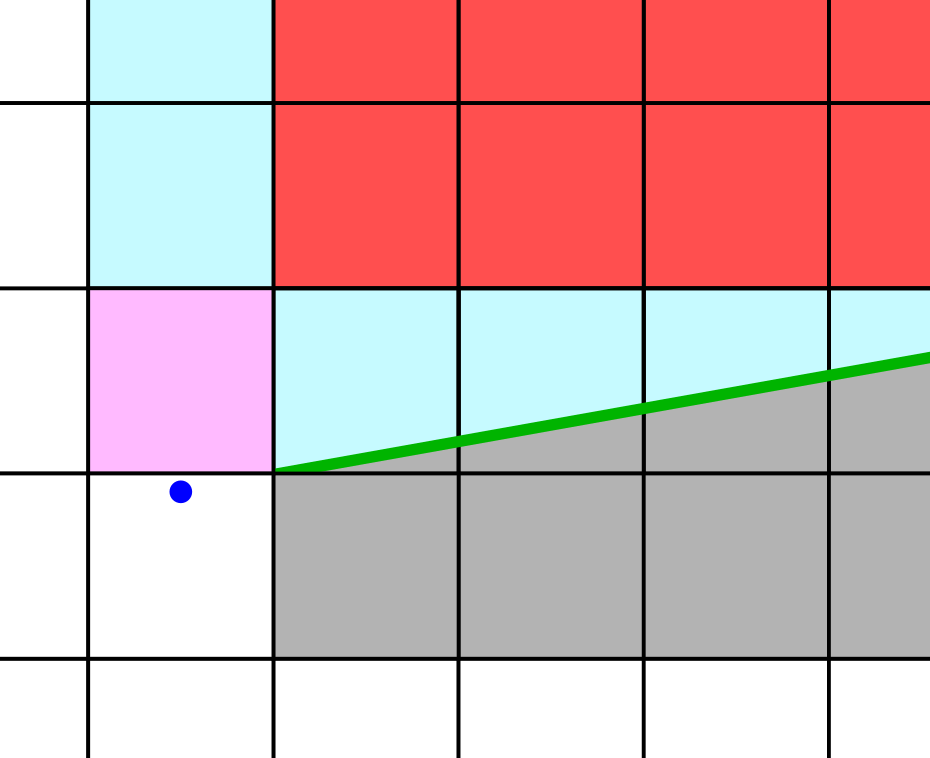
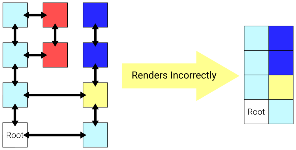
However, this does not yet allow us to render the entire scene. Consider an intercardinal region without an immediate intercardinal split. This is depicted in the image below. From the root’s perspective, the red and blue tiles overlap. However, if only the cardinal and intercardinal rendering procedures – as described above – are used, the red region is not rendered. In this post, I call regions like the red one “hanging”, as they effectively hang to the side of a cardinal corridor.
When rendering an intercardinal region without an intercardinal split, these hanging regions should be rendered first. I do this by looking for intercardinal splits while traversing a cardinal corridor. If such a split is found, only the upper part should be rendered as a “hanging part”.
This is displayed as only the red region in the left image, which is rendered like any other region with an intercardinal split. However, only the “upper” part (residing along a cardinal corridor) is rendered. The part below the clip-half-line ought not to be rendered just yet. After all, it could have its own splits. To ensure the lower region is rendered correctly, the inverse of the hanging region’s clip region is given back to the caller, which ensures that it will not overwrite the hanging region. (Note that the caller is rendering a non-splitting intercardinal region)
Conclusion
All these steps together should be sufficient to render the two-dimensional doubly linked list of tiles as a non-Euclidean grid. I hope my ramblings about cardinal corridors and intercardinal splits made some sense. At the very least, I laid out the peculiar cases to consider (with pictures) when implementing such a renderer.
This is a small project I implemented for fun a long time ago. I currently have no intention of using it further but would surely be interested in seeing it applied in projects by others.